
The chassis of the Kart and its suspension went through many, many sweeping iterations throughout the design process. Originally, it was designed around an active aero fan-assisted floor, and was intended to have no suspension, and purely operate as a 0-60 car. However as the design progressed, it became clear that this was simply not viable with the power to weight ratio the vehicle was capable of. It needed suspension.

I put a lot of work into this design, my first attempt at making a chassis, however the aero platform ended up being less viable than I had hoped due to fan availability, and the drive train more expensive than I had hoped as well. In addition, the new design called for a four-link drag suspension set-up, which was as complex and costly as the independent double wishbone suspension I wanted but decided against for that reason to begin with.
Faced with the option to either scale back the project and create a very questionable but easy to make go kart with 200 horsepower, or make the race car I had always dreamed of, I consulted with my team and we decided to jump off the deep end and completely scrap the design in favor of a track vehicle. No regrets there. However it did require a full redesign of the chassis.
As mentioned in my suspension page, for the new design I began with the suspension pick-ups, already knowing the weight distribution I was targeting at 54:46 rearward bias, as well as the aspect ratio 1.7:1. There was some alternating back and fourth between suspension changes and chassis changes for packaging reasons, and preliminary FEA, as can be seen below.


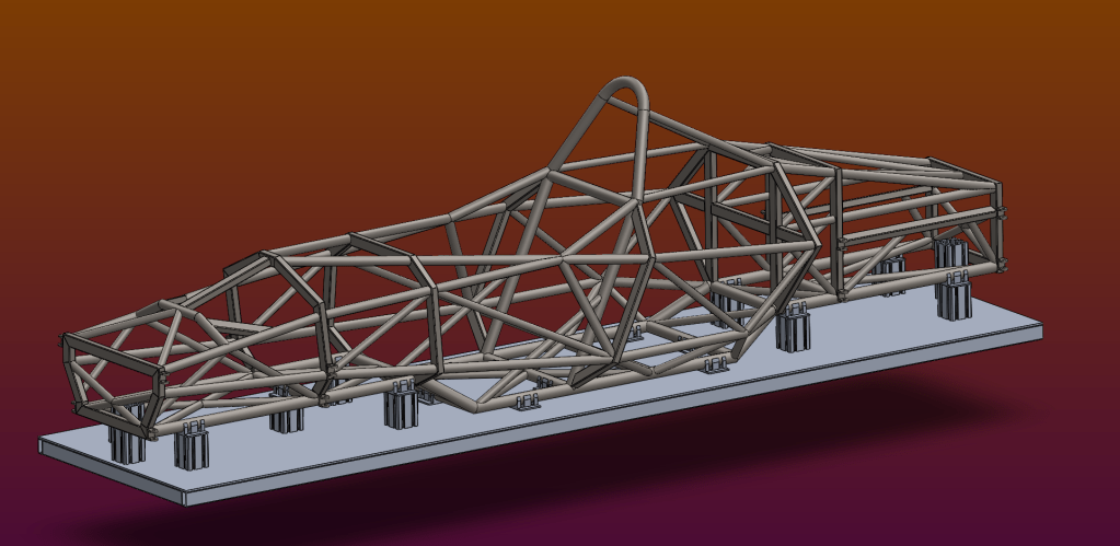
Finally, after much back and fourth I settled on a design. The design was mostly optimized geometrically based on the forces I found in my suspension calculations, to the best of my ability. FEA was then used to verify its integrity and improve the chassis where necessary. The rear end lower rails ended up needing some changes, as well as the rear suspension upper pick ups. It was difficult to keep the weight distribution far enough forward with such a heavy power unit. The entire chassis had to be shortened to achieve a decent aspect ratio for handling, a low enough curb weight, and a suitable weight distribution for a high downforce ground effect vehicle.

This FEA trial shows the performance of the chassis under 4G aero load, in a 4G corner, on exit. The worst possible conditions for this particular design, yet it is well within the margin of safety for that rod length as verified by simulated strain and external buckling calculation. Torsional stiffness was very good for the front end, with less than 5mm of deflection at peak loading, with slightly more lateral flexibility on the rear. An undesirable trait under acceleration, which is why the upper rails will be modified somewhat from this design, along with the secondary support rails in the lower section.
The chassis main rails, on the bottom, as well as the driver roll hoop are comprised of 1.5in OD 0.095 wall tube sections for greater bending stiffness, as they bear most of the load from the suspension and aero. The rest of the vehicle is constructed from the much lighter 0.065 wall sections, of 1.25in OD, 1.0in OD, and 1.5in x 1in square sections. The 1.25s make up most of the longitudinal upper rails, and some heavy load bearing cross members. The square stock was used for all of the roll hoops besides the driver safety hoop, because it made fabrication much easier, and provided improved strength in some areas given our lack of access to a tube bender. Many of the roll hoops have the longitudinal rails drilled and passed through them, providing a continuous structural element that improves stiffness of the car at the same weight. The 1 OD sections make up the tertiary supports, providing extra stiffness to the main load bearing frame at a much lower weight cost. They are short in length, so the loss in second moment of area and thus potential for unsupported length is not a problem.
Next came the fabrication concerns. As we are a completely self funded and self made team, we had no access to a proper chassis table, and lacked funding for the large thick plate steel needed to create one. We were forced to improvise by constructing our chassis table with smaller rectangular mild steel stock, and some quarter inch aluminum plating for the surface. It was more annoying to create, and required more floor supports to accurately level and flatten to the tenth of a degree, but we were able to design and construct it within a week. It uses precision aluminum extrusions for standoffs to mount the chassis rails in, which ended up being successful when it came time to weld the lower rails.

Following the construction of the table, I rigged a milling machine to act as a versatile and highly accurate pipe notcher. Chromoly tubing is hard to cut, running through it with the mill’s headstock feed exploded a few hole saws, so we opted to turn the head along the bed auto feed and use that. It looks ridiculous but it works perfectly. 3d printed alignment jigs were used to ensure accurate rotational positioning of the notches in complex cluster joints at unconventional angles.

With this machining method, we were able to successfully cut and weld the bottom rails of the vehicle in just 2 weeks. Roughly thirty percent of the chassis. Much of the rest of it is comprised of miter cuts, so it won’t take as long to finish it out especially now that we have a set workflow.
